 Kapitel 5
 Kapitel 5
A computer program consists of a series of instructions or statements in a selected programming language. A computer executes each statement in a program and perhaps displays the results of its execution process. In order to write programs that do all the things that are desired and that do all the desired things correctly, it is extremely useful to develop programs in a modular fashion.
It may be helpful to consider what we normally do when confronted with a problem such as: buy fruits. We immediately think of subtasks: need money to pay, select fruits, transport, and others. Perhaps the next thing we may do is to order these subtasks, i.e. which subtask needs to be done before any other subtasks. For example, we cannot pay for the fruits before we have selected the ones we need. Modular program development follows a process that is quite similar.
The concept of modular program development is very simple and very powerful. It involves dividing a task into smaller subtasks and then developing solutions for each of the subtasks. A subtask may be divided into further subtasks and so on. The advantages of this strategy in problem solving (since that is why we write computer programs) are two-fold. First, it is easier to find a solution for a small problem than a bigger one. Second, it is possible that the solutions developed for smaller problems (or subtasks) of one big problem may be reusable in another big problem.
While modular programming provides a good strategy for developing and writing programs, two additional concepts need to be understood as well. These are data models and control structures supported in a specific programming language. .c.5.2 Data Models Computer programs manipulate data like numbers, characters, strings, lists, and others. Further, there are operations on these data that are supported in a given programming language such as two numbers can be added, two character strings can be compared for length or similarity. These issues are referred to as the data model of a programming language.
Consider the problem of buying the fruits. We need a list of names of fruits (i.e. character strings), amount of each fruit we wish to buy (which may be a whole number like 6 bananas or a number with fractions like 1.25 kilograms of berries). Further, we may have a list that we consult during the shopping trip and upon which we tick off each fruit as we take it off the shelf. These are the different kinds of data types we normally use in computer programs.
An additional thing to note here with the example of shopping for fruits is that we keep a list of fruits from the start till the end, i.e. it is available at all times during the shopping trip. In computer programs such data items are referred to as global variables. On the other hand, while selecting the berries, we may look for one kind of color or smell, and for the bananas, a different color or smell. These kinds of data items in computer programs are referred to as local variables, i.e. data that are useful in one context but that are different or not needed in another context.
The program planning techniques that are introduced here use natural language to describe the structure of a program. Flow charts and structure diagrams employ visual aides as well. All of these techniques help to organize a project and to isolate possible flaws in the logical structure of a problem solving strategy. They may also reveal opportunities for streamlining a program. At least one of these techniques should be employed to fully outline a new programming task before ANY programming is done.
Actions that are described more than once in such a description, indicate the chance to write a general operation that can be used for all required occasions. For instance, "Go home" appears four times in the above pseudo-code, indicating a cancellation or successful conclusion of the Buy Fruit program. By checking if all (or any) of the desired fruit has indeed been purchased, a single, generalized go_home function can be written to fit all of the situations in which it might be called.
The degree to which a given programming task should be expanded depends greatly on the complexity of the given task and the programmer's own experience. The goals are clarity, simplicity and legibility.

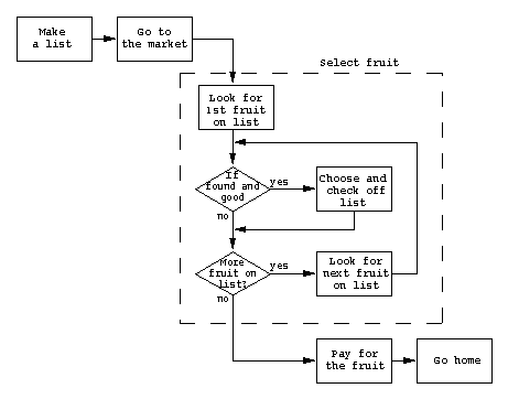
Statements or structure blocks indicate either a definitive action, a further subset of the program code or an entire program. Statements are limited to one entry point and one point of exit each. Sequential programming is depicted by linking two or more statements together. Conditional constructs are indicated by diamond shapes that also have only one point of entry, but have more than one exiting point. Loops are indicated by combining a sequence of one or more statements and a directional arrow that connects the exit point of the last statement to the entry point of the first statement in a loop. The following is a flow chart equivalent to the simple form of the pseudo-code illustrated in the previous section:

Each statement or structure block of this flow chart an be extended into a more detailed representation. The following illustrates an expansion of the Select fruit statement:

Notice that the expanded statement, like the original, also has only one point of entry and one exit. The expanded version must require and produce exactly the same information that the simpler statement does. In this example, the *fruit_list* variable, created while executing the statement Make a list, was required in order to perform the action indicated by the first substatement of Select fruit: Look for 1st fruit on list. The *fruit_list* variable is also altered during the course of Select fruit, if fruit on the list is indeed found and selected. By passing the updated version of the *fruit_list* variable out of Select fruit, and into the next statement, Pay for the fruit will be able to check what must be paid for.

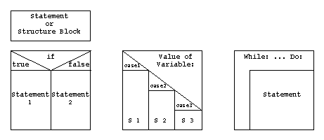
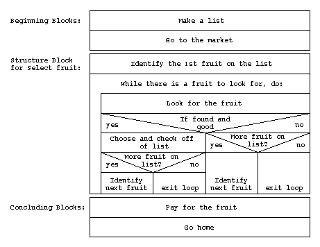
As in the case of flow charts, statements can represent specific actions, subdivisions of a program or entire programs. Statements can be constructed out of any legal combination of the control constructs, as well as further embedded statements. Structure diagrams are built within a rectangular framework. This facilitates easy visual checks for completeness that the free form of a flow chart does not allow. The following structure diagram is equivalent to the expanded flow chart illustrated in the previous section.

Note that it is not possible to jump horizontally between statements or constructs in a structure diagram. All actions flow downward, with the exception of loops, towards the terminating bottom line. Complicated programs may require separate structure diagrams for substatements that can be referenced in the main diagram by number or name. Here too, it is important to remember that expanded structure blocks and their simplest statement forms must accept and produce the identical information and results.
This exercise consists of writing pseudo-code and creating either a flow chart or a structure diagram for the program you will be writing for exercise 6.
The Problem Statement for exercise 6 is the following: Write a program that draws a four cornered building with one of three possible roof forms. The program must be able to do the following tasks: Prompt the user to input the corner points of the building outline; allow the user to specify the height of the building; ask the user to select a roof type where the choices (flat, gable, hip or mansard) are signified by an integer; draw the building specified. Other variables such as roof height may also be necessary. The Mansard roof type is optional. (See the description of exercise 6 for further details.)
You should be able to use this pseudo-code as an outline for the next exercise. The pseudo-code should be expanded beyond the minimum level, but not be more than about a page long. Similarly, the flow chart or structure diagram can either be evenly expanded to a reasonable level or one part can be described in complete detail, while the rest remains in simple structure blocks. Spend time considering and documenting function and variable naming conventions. These can either be listed at the appropriate places in your pseudo-code or described separately.
Write the pseudo-code in a text file named 05_name.txt. Include a description of the naming conventions that you have developed for the task. The flow chart or structure diagram can be done in AutoCad (saved as 05_name.dwg), in any other program or by hand. Submit your finished files to /homes2/prog/abgabe. Charts or diagrams done in programs other than AutoCad or by hand should be submitted separately in paper form.
Prog Content Vorwort ..1.. ..2.. ..3.. ..4.. ..5.. ..6.. ..7.. ..8.. ..9.. ..10.. ..11.. ..12.. ..13.. Appendix